FDT-DTM Implementation for Smart Instrumentation (Hart)
Lab 2: FDT-DTM Implementation for Smart Instrumentation
Integration
Overview
The exercise is about FDT/ DTM implementation for integration smart instrumentation (HART supported instrumentation) into Automation system architecture.
Learning Outcomes
In the exercise, it will have some specific customer requirements scenario. By the completion of this lab the participant will be able to:
- To design and to decide the correct place/ platform to implement FDT/DTM in order to answer specific customer requirements in their whole life cycle of the project (engineering/development, commissioning, maintenance and operation
- To understand the drawback or limitation for each platform in term of FDT/DTM implementation in order to help participant to decide the correct platform.
This Lab Covers
Lab 2: FDT-DTM Implementation for Smart Instrumentation Integration 1
- Integration of HART smart Instrumentation in Automation System Architecture CONCEPT 2
- Exercise Scenario 5
- Exercise Implementation and Architecture 6
FDT/ DTM Implementation Design 6
Exercise System Architecture 7
- Testing the system 28
- Integration of HART smart Instrumentation in Automation System Architecture CONCEPT
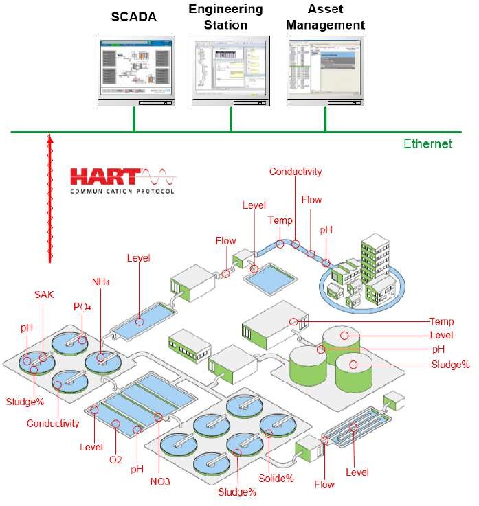
When customer already invested their money with smart instrumentation using HART protocol, we need to make sure that customer can get the benefits of having HART solution by understanding their real requirements. Normally by investing this smart instrumentation, customer requires to do remote diagnostic, remote calibration and remote configuration (asset management purpose) from correct platform in proposed Automation system architecture.
We should know some important points below in order we can help customer to design the solution that finally can bring all the values for them by having this HART investment for their whole project life cycle (engineering, maintenance and operation):
-
- In 1 HART network, it only can support 1 Primary Master and 1 secondary Master to be connected at 1 time.
The connection as Master is needed for example when the tool need to do remote diagnostic, remote calibration and configuration.
The Master can be engineering station, asset management system (like fieldcare, Pactware) using FDT DTM technology or even SCADA
-
- We need to really ask to customer or consultant whether they need HART data (PV, SV, TV, QV, etc) to be accessed by controller for control purpose or not. Does that HART data is important or useful for control system for example to be used in process control process?
For most of application, controller does not need to access that additional data. They only need to access Present Value (4-20 mA) data. For remote diagnostic, remote calibration, and remote configuration, customer will use asset management system using FDT DTM technology.
With this case, In Unity Pro (Controller programming software), we will implement this need like we implement the normal standard analog input and output. But we still need to put HART module. This HART module will be as gateway for Asset management to get the HART data from smart instruments. We need to still to put HART module DTM in order to make module is in functional status (not faulted status).
-
- But if customer need Modicon controller to be able to access HART data (PV, SV, TV, and QV, etc) for process monitoring and controlling process, then there are two options. First option is using DDDT (Device DDT) and using function blocks (elementary function blocks or derived function blocks).
- The request of HART data using DDDT (Device Derived Data Type) approach will not activate HART master connection from that HART module to smart instruments in that time. So if HART data is already in HART module itself, there is no active HART master will be activated in the network in that specific time.
- Using Elementary Function block (EFB) HART or using some DFB, then this approach will use Ethernet IP explicit messaging. It will use/ activate some HART command so it will activate the master connection.
If EFB requests this HART data every controller scan time, then it will activate HART connection from HART module to smart instrumentation every scan time.
-
-
- So when you configure DTM of this HART module in Unity Pro (or via PES) as Primary Master, then because that Ethernet IP explicit messaging most of time will be executed every PLC cycle time, Meaning the primary master connection will always be activated.
- The impact here, if we have external asset management and to be configured as Primary Master (normally it is configure as Primary master in order to really access until level of instrumentation), then Asset management HART connection will be rejected because HART can not have 2 Primary master at 1 time.
- Because of that, to avoid this condition, when customer have Asset management, we need to make sure the configuration of DTM in HART module in Unity Pro (or via PES), will be secondary master
-

-
- It will be the same, when we try to do connection to DTM of HART module via unity Pro as FDT container. And use this FDT container to do connection via DTM tree configuration, then it will activate the HART master connection. So again if the system has dedicated asset management software, we need to make the configuration of DTM for that HART module inside of Modicon controller configured as Secondary master.
- When customer invest big money to have smart instrumentation in their plan, it is a clear indication that they would like to have remote platform that can do remote functions such as remote diagnostic, remote calibration, and configuration. We need to choose correct platform to answer this. That’s the time we need to offer asset management software platform that natively will do all that remote functions. We do have option for free asset management software which is Pactware.
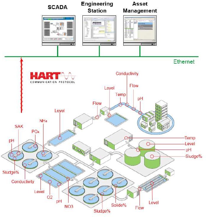
Customer requirements:
-
- For Controller and Supervision/ SCADA purpose, it requires to access HART data from analog Input smart instrumentation. It requires to access Primary Variable (PV), Secondary Variables (SV) and Third Variable (TV)
- Because they already invested big money to have all instruments with HART supported instrumentation, then customer requires to automation solution provider to have remote asset management platform that can deliver remote function such as remote diagnostic, calibration and configuration that they can use and do in whole life cycle of project.
- Customer requires when specific platform is doing that remote functions (diagnostic, calibration or configuration) in any time during project life cycle, it does not bring impact to running control system (Controller and SCADA) for example it will not force or impact the controller for example to make controller need to be stopped. No disruption to running control system, when customer does that remote functions (diagnostic, calibration or configuration by doing the modification to the DTM)
FDT/ DTM Implementation Design
In order to help you to design the smart instrumentation integration and answer customer requirements, please answer some question below. It will help you do decide the correct place/ platform to implement that FDT/ DTM technology.
-
- To answer requirements above, do we need HART module (in this case Analog Input HART module) into controller system?
- To answer requirement, point 1 above, do we need to put/ add DTM for that HART module into controller programming application?
- What do you suggest to access that HART data to answer requirement point 1? Do you prefer using DDDT (Ethernet IP implicit messaging) or using function block? And Why?
- In DTM HART module configuration, what does the connection HART type that we should implement? Is it secondary master or primary master? And why
- To answer requirements at point 2&3 above, which will be the correct platform that you suggest to be used for answering those requirements?? Do you suggest to use Unity pro as correct platform?
Answer for Questions above:
- Yes because the platform components need to access HART data for control system and for remote functions (Diagnostic, calibration and configuration)
- Yes, with current solution situation, it is obligatory to put DTM of HART module and configure correctly the FDR service in order to make the module will be in functional status (not fault status). because controller need HART data in this case PV, SV and TV, then we need to configure this HART data too at HART module DTM.
- DDDT (using Ethernet IP implicit messaging). It is simpler and it will not activate the HART master connection
- Secondary Master. Because we will have the other platform which is Asset management to be Primary master to do remote connection
- No, Unity Pro is not the correct platform to answer that requirements. Specially to answer requirement number 3. We need to offer platform that really natively design to do that specific remote functions (remote diagnostic, calibration and configuration). We will offer asset management software to do that functions
Exercise System Architecture
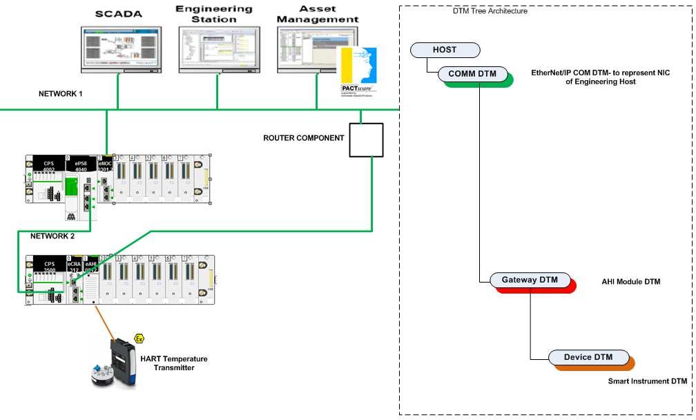
Note: because of limitation of hardware for exercise, please make sure that Asset management software is in the same network as HART module. We might not have router component in our exercise hardware. We might build only 1 network for the whole system.
- Configuration in Controller Part
- Please make sure you configure hardware configuration based on hardware availability.
- Please design correct IP address for CPU, communication module and HART module.
- Please enable security service needed.
In controller configuration, we need to make sure the security for CPU will be ok for ERIO configuration purpose. For that purpose, we need to make sure that TFTP, EIP, DHCP_BOOTP setting are enable for ERIO architecture. Plus we need to make sure that FTP is enabled when we add HART module into controller
In order, not to have problem with accessing to controller while we are testing it, just disable the access control
-
- After that, you can add AHI module in local rack (for standalone controller) or in Remote IO drop (depend on hardware availability for the exercise). If you put HART module in local rack, you will have 2 choices for IO data type. Please choose Device DDT as I/O Data Type. For Hart module in ERIO, the I/O data type will be always Device DDT

-
- The smart instrument in this case Krohne TT51 will be wired to 1 channel of AHI module. You can configure the AHI module for example by changing the type of signal and scale.
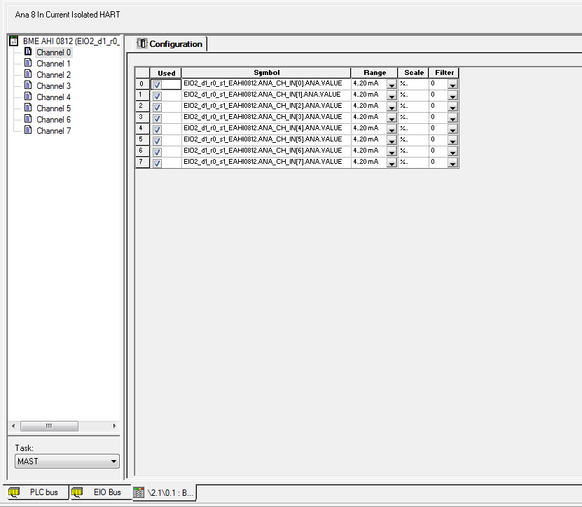 Right now just please make sure the type of signal is 4..20 mA
-
- Add DTM for this AHI module. We need to add DTM for this AHI module, because controller need to access HART data (PV, SV, and TV) from Krohne TT51.
In my example, I added AHI module at ERIO drop 1.
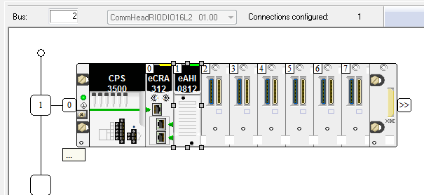
We would like configure that controller will access that HART data using DDDT approach. So it will use Ethernet IP implicit messaging.
You can decide who will be the scanner/ consumer of this IP Implicit messaging. It could be CPU or communication module (ENOC).
For example in this exercise, we will configure M580 CPU as scanner of Ethernet IP implicit messaging. So you need to add DTM for AHI in CPU part.
The DTM for AHI module will be Gateway DTM.
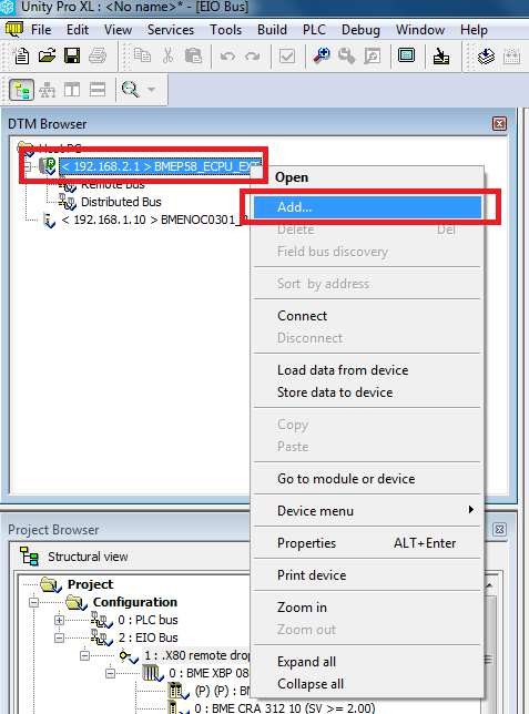
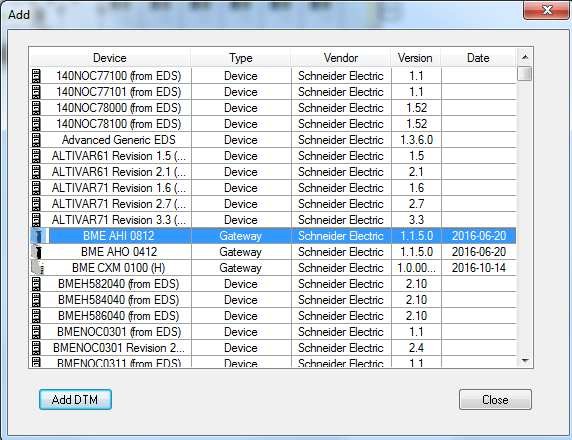
-
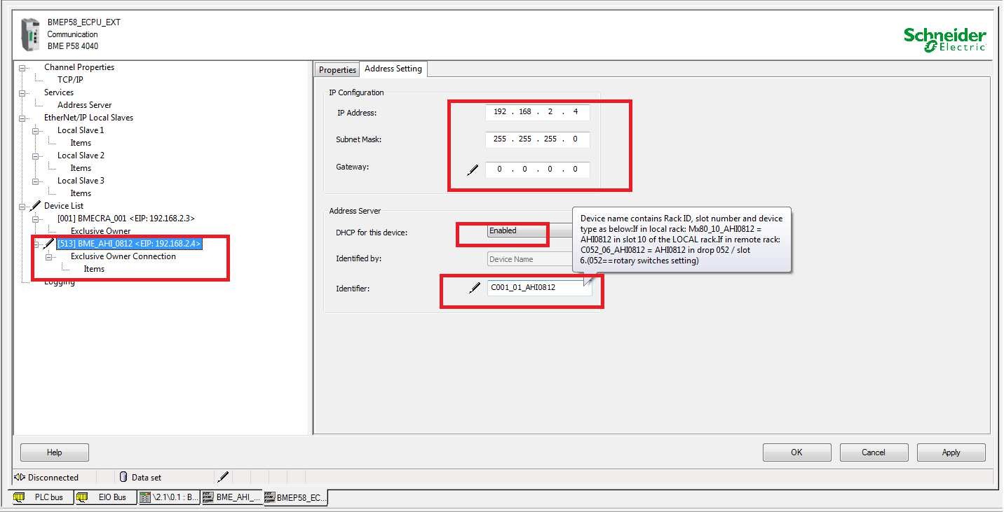 Go to DTM configuration of CPU in order to give correct IP address for this AHI module and enable the address server in order to link that added AHI DTM to correct AHI module in the ERIO drop.
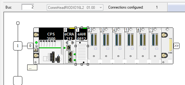 Because I put that AHI module at drop 001 and slot 01, then the identifier is C001_01_AHI0812.
Please make sure the IP address for AHI module is in the same network at ERIO network.
-
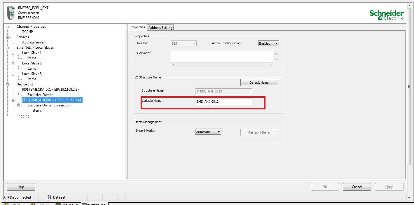 In properties tab, you change the variables structure name for this module in order to make it more user friendly.
- Go to DTM configuration of AHI module. In module overview, please make sure this module will have HART secondary master connection. It is because we will have Asset management software that will do connection to HART instrumentation to do some remote function, its connection will be primary master. Even thought, the accessing HART data for controller using DDDT will not activate HART connection. But we need to avoid when someone do HART connection from Unity Pro as Primary master so it will reject the other connection as Primary master for example from Asset management software
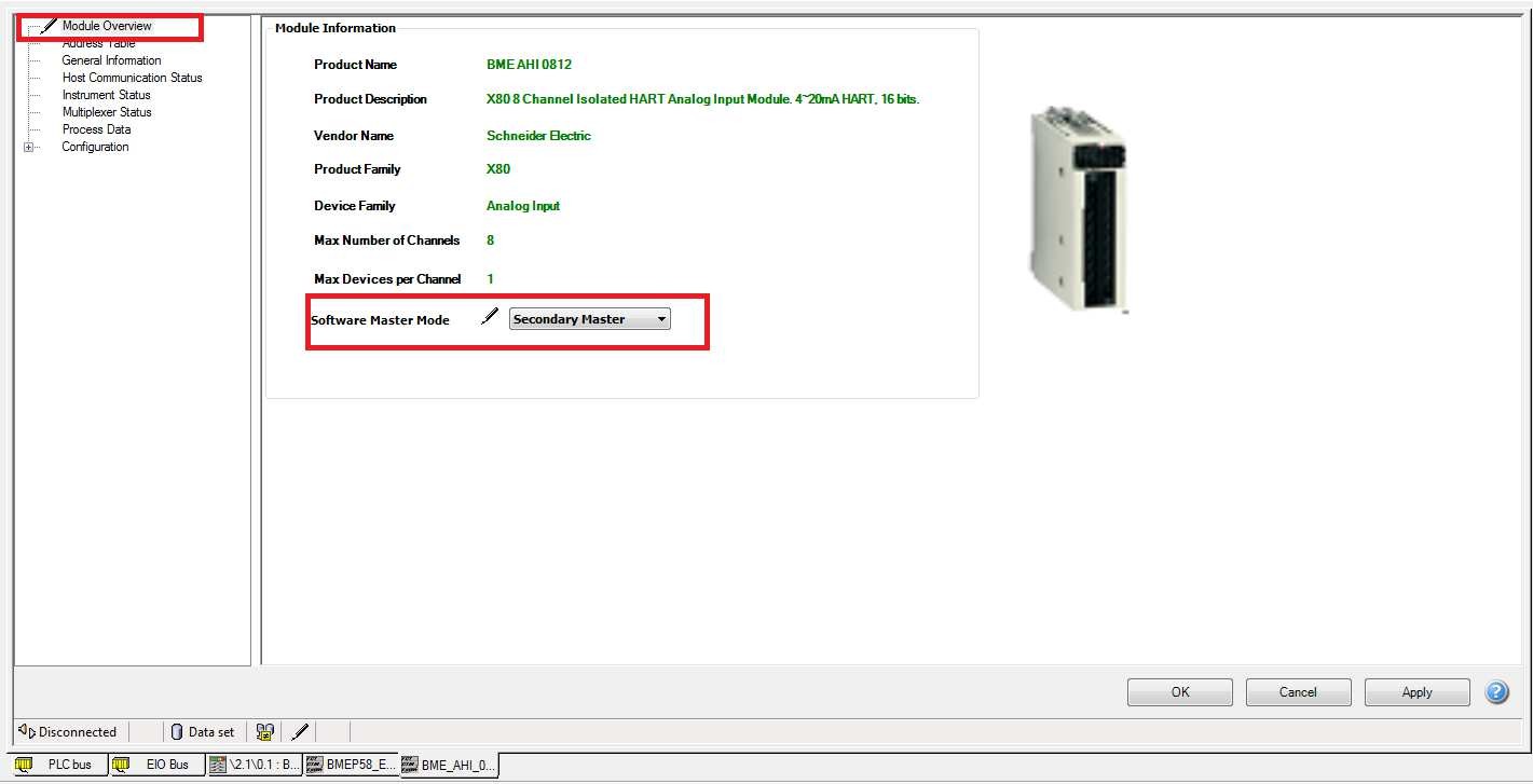
-
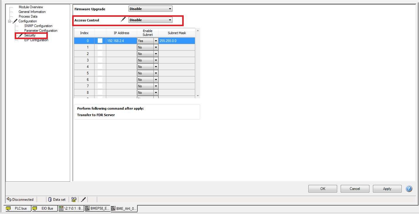 In configuration tab->security. Please disable access control. This one is order to avoid any problem while doing exercise when Primary master or secondary master of HART trying to do connection
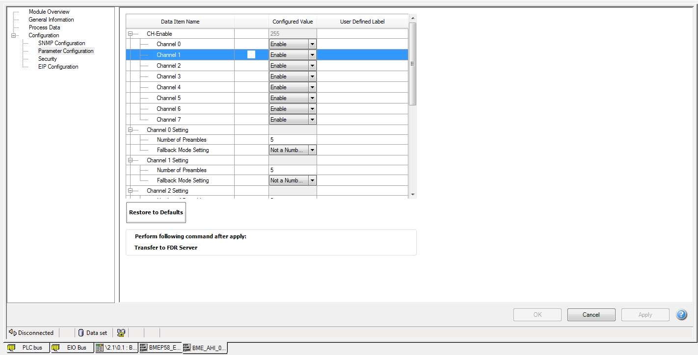
- In configuration->parameter configuration, please make sure the channel that you want to use and wired to smart instruments is enabled
-
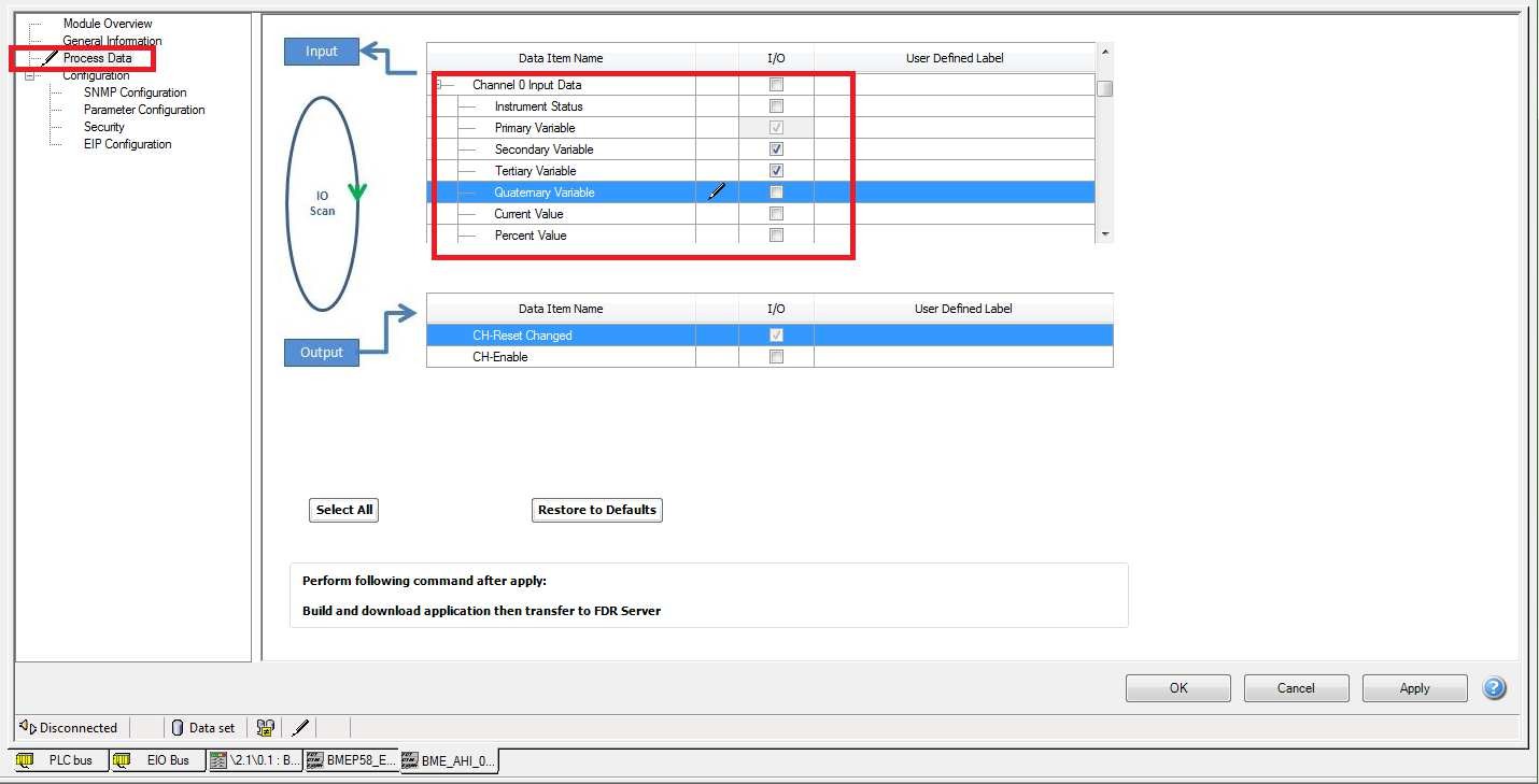
- In process Data, here we can configure what kind of HART data that controller need to access. For example that Krohne TT51 is wired to channel 0. Because controller need PV, SV and TV from Channel 0, then just activate those HART data.
-
- Close the DTM configuration and you can build the application.
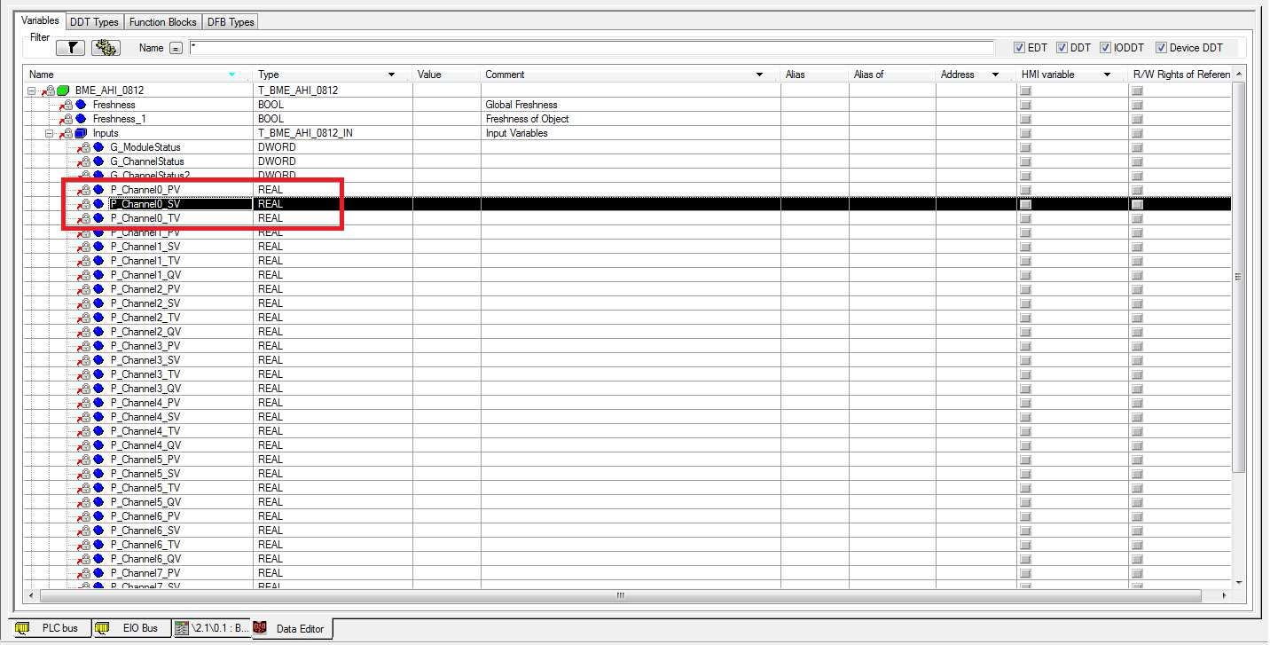 If you go to Unity Pro data editor, you can see that Unity Pro create Device DDT structure based on your configuration
- Download the application to controller
- From the AHI DTM, perform ‘transfer to FDR server.
With this step, the FDR agent (in this case AHI DTM) will transfer its parameter configuration to FDR server (in this case Controller CPU/ COMM module). Now you can connect to DTM online.
- Configuration of Asset Management Software
- In this exercise we will use Pactware 5.0 as free asset management software in order to do the remote function (remote diagnostic, calibration and configuration) for smart instrumentation integration in order to answer customer requirements explained in above scenario.
- With Pactware 5.0, the default installation will install all needed DTM (com DTM, Gateway DTM, device DTM) for Schneider Electric Components (M580 CPU, eNOC, HART module, Altivars, etc)
- But for Pactware 5.0, by default installation it does not have specific DTM for Krohne TT51. Because of that you need to install DTM of that smart instrumentation into the station where you install Pactware 5.0. You can get the DTM for Krohne TT51 from Krohne website. If you use the virtual machine from Texpert, the DTM for Krohne TT51 already been installed there.
- Plus for Pactware 5.0, by default installation, it does not install specific COM DTM that will be use for this exercise (EtherNet/IP COM adapter DTM). This COM DTM will represent the NIC card of Asset management station. Please install it separately. Note: The TeXpert VM already has Krohne TT51 and EtherNet/IP COM adapter DTM installed.
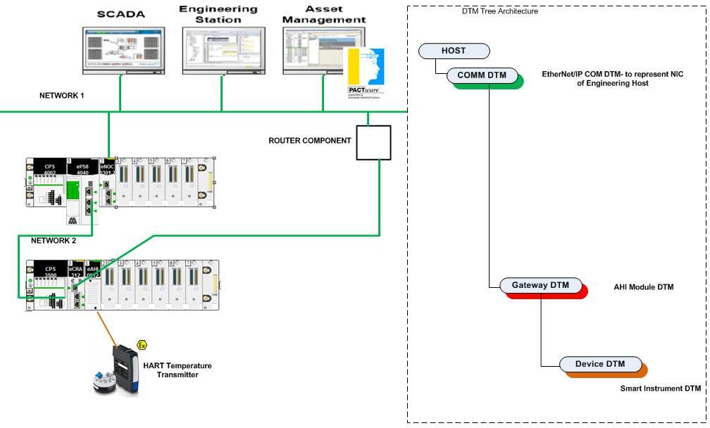
- This DTM tree architecture that we will build for this solution
-
- Open Pactware 5.0.
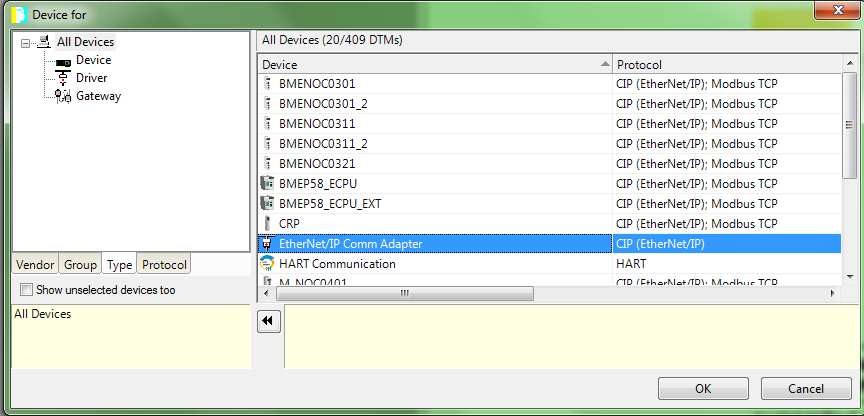
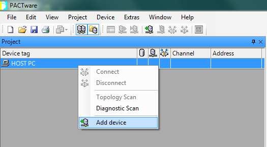 At host PC->Add device. Here we will add COMM DTM. In this case EtherNet/IP COM adapter DTM will be COMM DTM for this architecture. This DTM to represent the network adapter of Pactware station or the Network Interface card of Pactware station. So please make sure your host PC is in the same network later with gateway DTM which is AHI module DTM.
Choose: EtherNet/IP Comm Adapter.
-
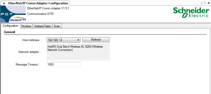
- Please make sure that you configure the EtherNet/IP comm adapter with the correct host address configuration
-
- We will use Topology scan function from Pactware. It is really useful function to build our DTM tree architecture.
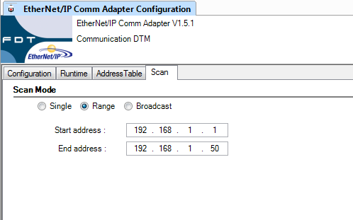 In the “scan” tab, please select range and put the start address and end address. You need to put the correct range based on your network configuration specially for AHI module IP address configuration
-
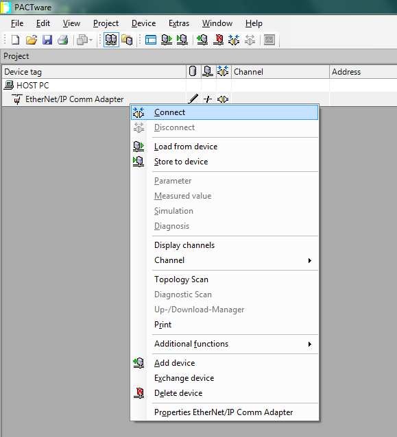
- Try to connect to EtherNet/IP Comm adapter
-
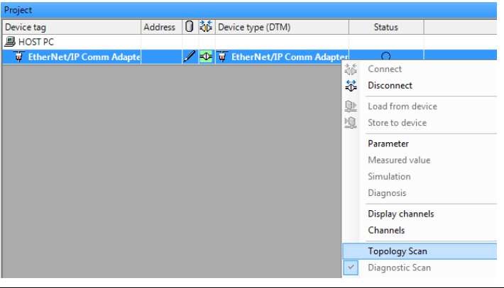
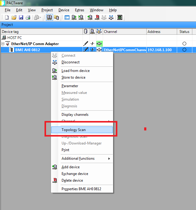
- After connecting successfully, the connection status will be green. Then right click on this device and choose “Topology Scan”
-
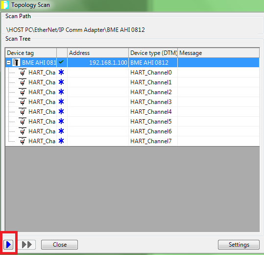
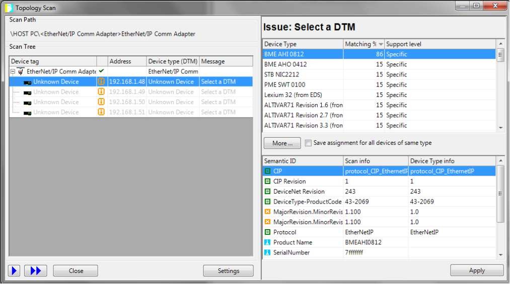 Click the blue Start sign to start the topology scan. It will scan the IP address as defined above. After the scanning, it will show the devices and you can choose the matching DTM according to device information. In this case, the BME AHI 0812 would be selected
- The result will be something like below

-
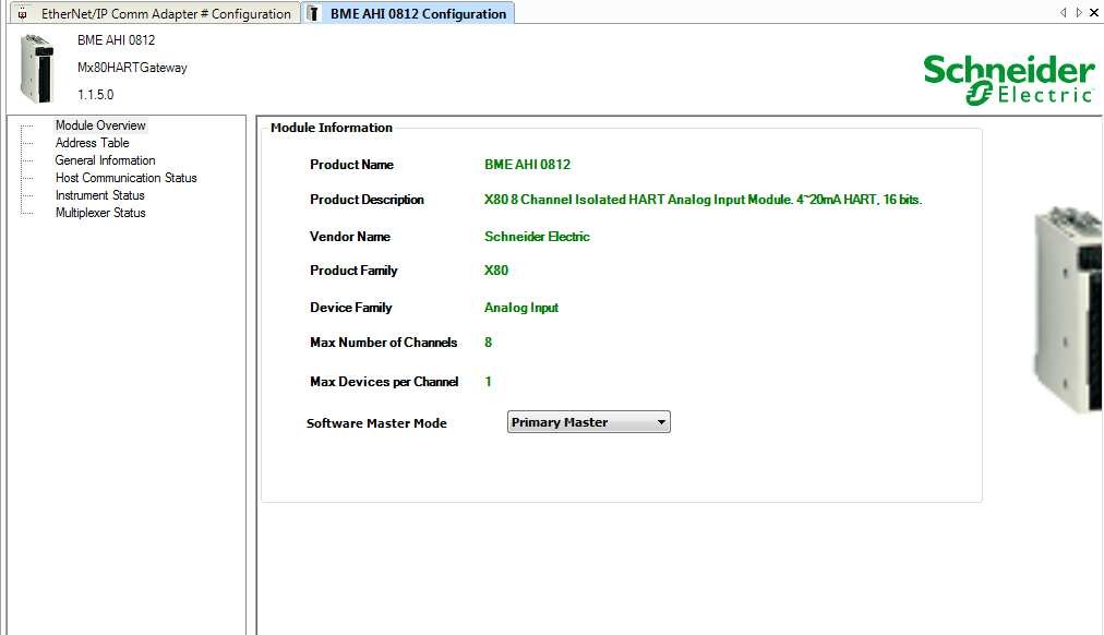 Please make sure the HART connection for this DTM will be primary master.
- At AHI Module DTM, You can try the same thing by doing “topology scan”
And click start blue sign button
-
 For example if channel 0 of AHI module is wired with Krohne TT51, you can link the DTM of Krohne TT51 to the correct channel of AHI module. The result will be something like this
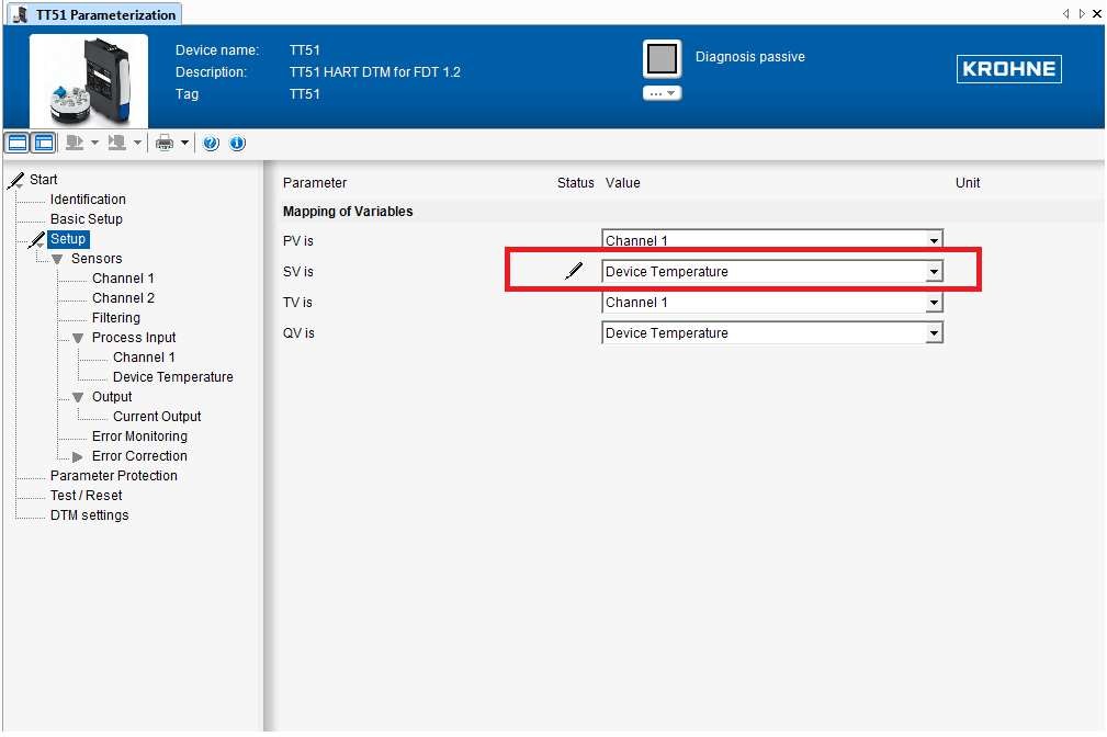
- By double clicking at that TT51 DTM, you can change the configuration of that TT51. For example we will configure SV as device temperature
-
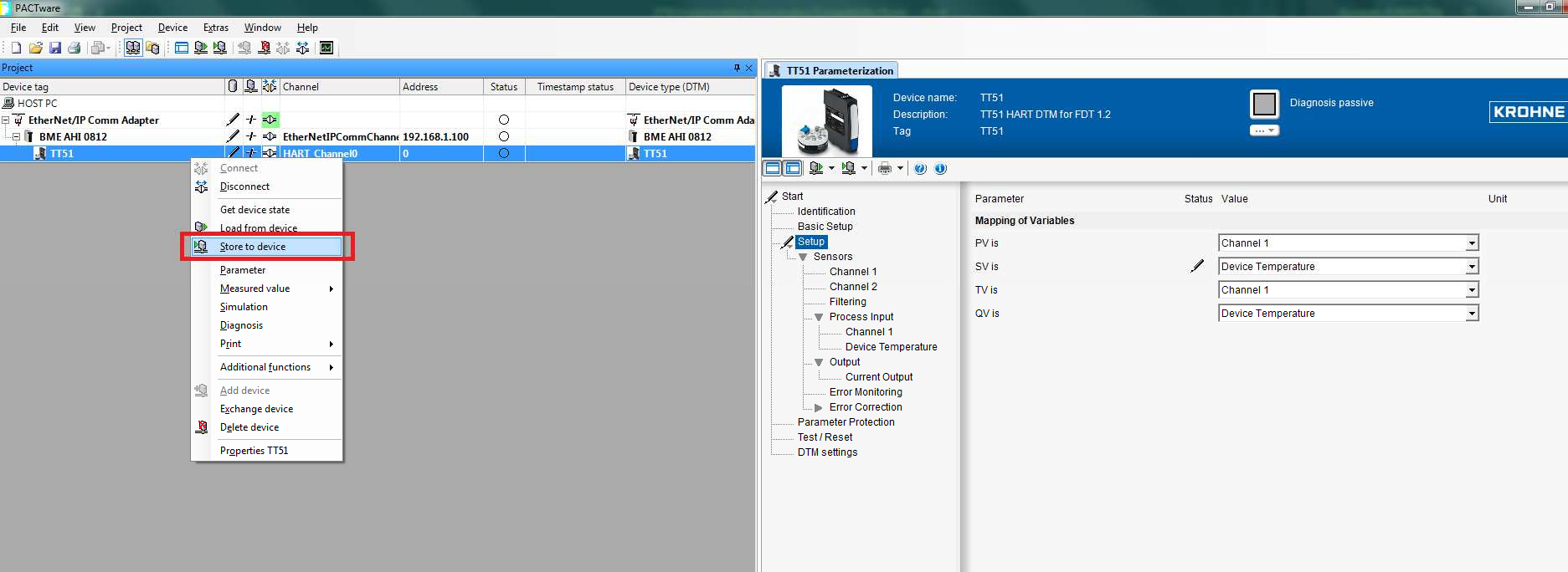 Once you finish the configuration, you can try to connect to that HART device TT51 and do “store to device”. With this one actually we do remote configuration function from asset management software
- xix.
You can create an animation table. For channel that is wired to TT51 module, you can check the value of SV variable. It should have the value of “device temperature” from the sensor
-
- Testing in Pactware side
You can connect to TT51 and do some remote diagnostic function and configuration modification function. All the modification of TT51 DTM will not have any impact to running control system (controller and supervision).


Responses